We have a massive range of engine bearings fo Cars, Vans & Trucks. We keep all well know brands including ACL, AE, Glyco, Vandervell, Mahle, King, Miba & KS (Kolbenschmidt)


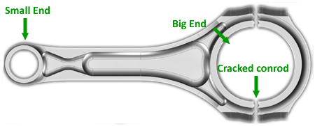
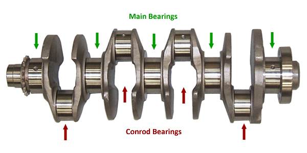
Commonly known as big end bearings, the connecting rod uses ‘shell’ bearings in the larger journal hence the title ‘Big End’. This refers to the larger end of the connecting rod which attaches to the crankshaft and is bolted together using high tensile bolts. The Main bearings are the ‘shell’ bearings that hold the crankshaft in place. Some main bearings use separate thrust washers and other engine designs have an attached or integral thrust washer built into the shell bearing, this stops the lateral movement of the crankshaft. Lateral movement is commonly referred to by engine builders as ‘end float’ or ‘End Play’. This is the side to side or thrust movement of the crankshaft, excessive end float can result in problems with the transmission or engine timing.
Engine bearing failure can be a result of various problems, usually, you can tell the problem with the engine by how the bearings have failed. Please see our trouble tracer guides for more information regarding bearing failure.
Big End Bearings / Conrod Bearings
These are the bearings that are located in the larger end of the connecting rod. Some shells will have locating tags which protude outwards that will slot into a machined area of the conrod. Some conrods are "cracked or snapped" generally bearings for this style of conrod do not have locating tags. The bearing is held in place by the crush of the conrod cap when it is correctly torqued. Many bearings have an oil hole in the upper shell to help with lubrication. The hole in the bearing is aligned with the hole in the conrod.
Main Bearings
These are the bearings that sit on central journals on the crankshaft.The crankshaft spins inside these bearings.Many main bearings have oil grooves and oil holes to keep the crank and bearing lubricated. Each engine is different and have different configurations of grooves and holes. Some main bearings have an integral thrust washer whilst others engines may have separate washers.
Thrust Washers
The thrust washers help align the crankshaft in block laterally. The thrust washer is designed to govern the amount of end float the crankshaft has. If the thrust face gets worn, you may need oversized thrust washers to decrease the end float back into the required tolerance.Small End Bearings / Bushes
These bushes are located are located in the smaller diameter of the connecting rod. These are pressed into the rod and often come with a new conrod. On older vehicles these were more easily replaced. Some small end bearings come as a standard size whereas other are UNB (unbored) These bearings will require boring out to the correct size to the gudgeon pin leaving the desired clearance set by the engine manufacturer.Camshaft Bushes
Some engine require camshaft bushes or bearings. These bearings sit in the cam caps. Not all engines have camshaft bearings. The most common engines we know that are fitted with these bearings is the Volkswagen Audi Group 4 & 5 cylinder TDI PD Pumpa Duse engine, along with the Ford Pinto & Crossflow.Engine Bearing Replacement
Engine bearings are fitted to the crankshaft and connecting rods, these bearings support the crankshaft and connecting rods enabling a film of oil between the bearing surface and the crankshaft journal, this enables the crankshaft to turn freely.Commonly known as big end bearings, the connecting rod uses ‘shell’ bearings in the larger journal hence the title ‘Big End’. This refers to the larger end of the connecting rod which attaches to the crankshaft and is bolted together using high tensile bolts. The Main bearings are the ‘shell’ bearings that hold the crankshaft in place. Some main bearings use separate thrust washers and other engine designs have an attached or integral thrust washer built into the shell bearing, this stops the lateral movement of the crankshaft. Lateral movement is commonly referred to by engine builders as ‘end float’ or ‘End Play’. This is the side to side or thrust movement of the crankshaft, excessive end float can result in problems with the transmission or engine timing.
Engine bearing failure can be a result of various problems, usually, you can tell the problem with the engine by how the bearings have failed. Please see our trouble tracer guides for more information regarding bearing failure.
Installation Guideline
- Before removing a bearing cap. Ensure matching connecting rod and main bearing caps are identified with the correct position number before they are removed from the engine.
- Check crankshaft main journals and connecting rods for size, shape, and surface condition using an outside micrometer. If any specs are found to be out of tolerance, have a qualified machinist correct them. Before doing any crankshaft journal resizing, check with L.E.C for available bearing sizes. It is also good practice to inspect the crankshaft thrust surfaces for possible wear.
- Cleanliness is one of the most important aspects of engine repair. Both engine block and crankshaft should be free of any dirt or debris. Use a wire brush to clean all oil passages. Thoroughly wash all of the engine components with hot soapy water, removing any built-up oil or carbon before assembly. Dry all components with compressed air to remove any lodged debris, this will ensure no dirt can enter the oil and cause future problems or failures.
- Carefully clean and install each bearing half into its appropriate position, modern bearings are produced without locating tags which require careful fitment, you can refer to the manufacturer's catalogue or contact L.E.C for fitment and bearing position information. Firmly push each bearing into its bore until a slight snap is felt.
- Ensure that all bearing oil holes line up with oil supply holes in the block. Also, make sure locating lugs where fitted are nested into their appropriate slots and each bearing lines up properly in its bore
- Apply a sufficient amount of bearing assembly lube, we recommend the use of Graphogen assembly paste, Graphogen provides an excellent safeguard against the potential rubbing or scuffing of metal components and is the first line in protection until the oil pressure is obtained. If the engine is fitted with PTFE oil seals make sure the crankshaft surface is clean and free from oil where the seal sits, this will ensure the seal can seat itself correctly once installed. Please see our separate guide for correct PTFE Seal fitment.
- Crankshaft Installation. With the engine block in the inverted position, carefully lower the crankshaft into the upper main bearings.
- Take extra care to prevent possible damage to the upper thrust bearing. Assemble and tap each main cap into its appropriate position making sure the caps are firmly seated and facing the correct direction. Clean and lubricate all the main cap bolt fasteners, this will ensure accurate torque readings. With a pry bar, push the crankshaft towards the front or timing end to align the thrust bearing surfaces. Hand tighten each main cap bolt then with a good calibrated torque wrench, torque each fastener starting at the centre main and working toward each end, torque each bolt to the specified load or setting. The shaft should turn freely after each tightening sequence. Check for proper oil clearance before final assembly, we recommend the use of Plastiguage to ensure correct clearances are obtained.
- Check Crankshaft End Float / Play. If you have a dial gauge, Install the gauge onto the snout end of the crankshaft. Force the crankshaft to its most forward position and set the dial to zero. Force the crank in the opposite direction till it bottoms out and read the dial, this will give you the end float measurement to then check the tolerance. A feeler gauge can also be used in place of a dial gauge.
- Connecting Rod to Crankshaft installation. Lubricate the rod cap bolts using a quality lubricant, for the crankshaft journals and the cylinder walls, it is good practice to use Graphogen or another engine assembly paste. Carefully insert the connecting rod and piston assembly into cylinder bore until the rod makes contact with the crank pin making sure the piston and rod are installed in the correct direction. If there is an arrow on the top of the piston this will point to the front or timing end of the engine. Place the connecting rod cap to the rod and hand tighten rod cap bolts. Using a good calibrated torque wrench, torque the rod cap bolts to manufacturer’s specifications. Follow this same procedure for all cylinders. The crank should turn freely after each rod has been installed. Check for proper oil clearance before final assembly, we recommend the use of Plastiguage to ensure correct clearances are obtained.
- Prime the Engine to prevent a dry start and possible damage to bearing surfaces, even with the use of Graphogen it is good practice to ensure the bearing surfaces are correctly lubricated after initial start-up. The engine oil system should be completely filled with a high-quality clean engine oil and pressure tested. After a complete engine rebuild a mineral oil can be used as a running in oil to correctly bed in new components and prevent cylinder glazing. Priming the system can be accomplished using two methods. Spin test the engine with a pre lubricator or simply turn the oil pump shaft with a drill motor until adequate pressure is reached.

